
Introduction: what is an Earth Leakage Relay?
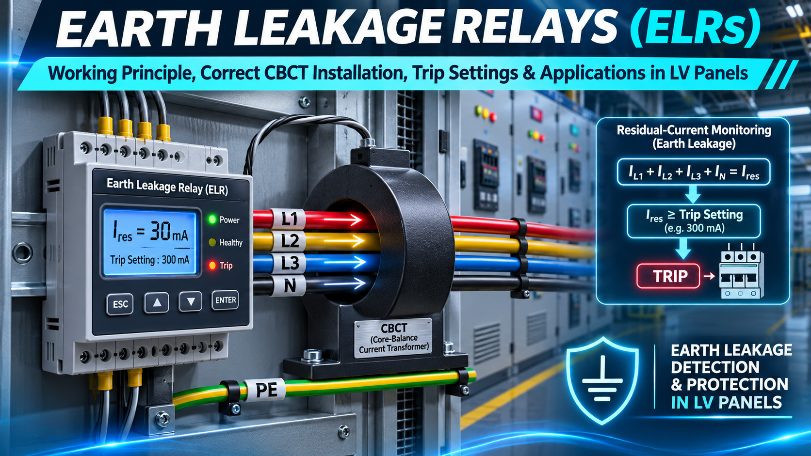
An Earth Leakage Relay (ELR) is a device that monitors unwanted residual current in an electrical installation. Where insulation fails, a damaged cable contacts earthed metalwork, or current flows along an unintended path to earth, the electrical currents returning through the monitored conductors no longer balance. The ELR detects this change using a suitable toroidal core-balance current transformer (CBCT), also called a zero-sequence CT.
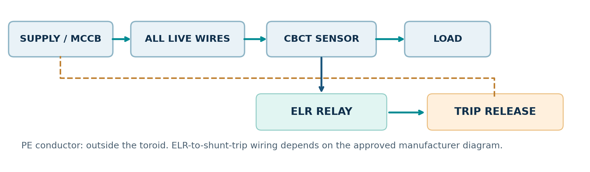
Unlike an ordinary MCCB overcurrent trip, which is intended to respond to overloads and short circuits, an ELR can detect relatively small residual currents that may not produce enough current to operate conventional overcurrent protection. The ELR itself normally provides a contact or control output; a compatible shunt trip, undervoltage release or appropriately designed switching arrangement performs the actual disconnection. [1, 2]
What an ELR system includes
- One residual-current relay with compatible supply voltage and adjustable or fixed settings.
- One manufacturer-approved CBCT sized for the complete group of monitored live conductors.
- ELR-to-CBCT connection cable and a suitable protected auxiliary supply.
- A correctly coordinated switching device (for example, an MCCB with shunt-trip release) and its trip circuit.
- Test/reset facilities, fault indication and optional alarm or remote monitoring connections.
How does an ELR work?
In normal operation the instantaneous algebraic sum of currents flowing through every monitored live conductor is approximately zero: IΔ = | IL1 + IL2 + IL3 + IN |. For a three-phase, three-wire load, the expression contains only L1, L2 and L3. An unbalanced three-phase load does not, by itself, constitute earth leakage when the corresponding neutral return is included.
If current leaks to earth and returns outside the CT window, a non-zero residual current remains. The CBCT produces a signal for the ELR. When the detected residual current exceeds the configured pickup level (IΔn) for the required time, the relay changes state. In a protection arrangement, its output operates the circuit-breaker trip mechanism.
Correct CBCT installation in a three-phase panel
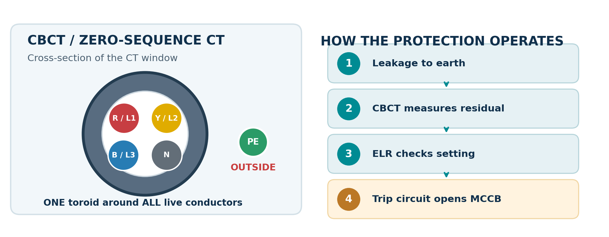
For a three-phase, four-wire (3P+N) feeder, route L1, L2, L3 and N through the SAME toroidal window, all in the same physical direction. For a three-wire feeder without a distributed neutral, route only L1, L2 and L3 through the window. The protective-earth (PE) conductor stays OUTSIDE the toroid. Use a matching CBCT specified by the ELR manufacturer.
Common installation errors
- Using one separate ordinary 200/5 A or 400/5 A metering CT per phase in place of the specified common CBCT.
- Passing the neutral outside the CBCT on a 3P+N circuit, creating a false imbalance when neutral current flows.
- Passing the PE conductor through the CBCT, potentially hiding earth-fault return current.
- Combining neutrals from different outgoing circuits or bonding neutral to PE downstream of the measurement point.
- Selecting a toroid with insufficient window clearance, incompatible input characteristics or unapproved extensions.
- Poorly routed sensor wiring, missing trip-coil supply, incorrect control-contact selection or an inoperative breaker accessory.
ELR sensitivity and time-delay settings
Two settings are frequently offered: IΔn (residual-current pickup threshold) and tΔ (intentional trip delay). Typical industrial devices may offer 30 mA, 100 mA, 300 mA, 500 mA, 1 A and higher pickup choices, together with instantaneous or adjustable-delay settings. Exact ranges vary by model.
Why time delay matters
An intentional delay can allow a downstream protective device to clear a local fault before an upstream feeder trips. However, time discrimination must satisfy the installation disconnection-time requirements. An upstream delay must never be introduced simply to stop nuisance trips where rapid disconnection is required.
Illustrative setting example
Suppose a distribution feeder uses an approved ELR system with IΔn = 300 mA and an intentional delay of 0.3 s. If a persistent residual current of 420 mA occurs, the relay is expected to operate according to its manufacturer-defined pickup tolerance and time characteristic, and the associated trip mechanism opens the breaker. The complete clearance time includes relay operation and breaker opening. This is a teaching example, NOT a proposed setting for a particular switchboard.
Special loads: VSDs, UPSs, inverters
Variable-speed drives and power-electronic equipment can generate AC, mixed-frequency, pulsating or smooth-DC residual currents. A standard type AC/A sensing arrangement may be inappropriate for some of these conditions. Select the residual-current technology (including type B where required) against the actual drive topology, filters, manufacturer instructions and protection design.
ELR versus RCCB versus RCBO
| Device | Detects residual current? | Interrupts current itself? | Overload / short-circuit protection? |
|---|---|---|---|
| ELR + CBCT | Yes | Normally no; uses external approved switchgear | Provided by separate MCCB/MCB or protective device |
| RCCB | Yes | Yes | No; separate overcurrent device is required |
| RCBO | Yes | Yes | Yes, within rated design |
| MCCB (standard) | Not necessarily | Yes | Yes; residual protection only if equipped |
Practical inspection and commissioning checklist
This distinction matters during panel specification. Fitting an ELR on the front door does not complete the protective system unless the sensing toroid, supply, wiring, trip release, breaker and functional tests are also correctly arranged.
- Confirm correct model numbers, ratings, auxiliary supply and CT/relay compatibility.
- Check the protective-earth continuity and verify PE does not run through the CBCT on this standard residual sensing arrangement.
- Check that all and only the protected circuit’s live conductors pass through the same CBCT, with neutral included where used.
- Confirm CBCT mounting, cable centering, terminal tightness and manufacturer-prescribed cable routing.
- Record pickup IΔn, intentional delay tΔ, relay output mode, trip circuit voltage and breaker accessory.
- Prove the trip release and its supply while following the approved switching/safe-isolation procedure.
- Use suitable calibrated residual-current injection equipment and verify relay operation and complete breaker disconnection where required.
- Record measured trip current/time, test method, equipment details, result and responsible tester.
A built-in TEST push button may check only the relay electronics and internal contact. It does NOT necessarily verify CBCT installation, remote wiring, the trip release, breaker movement or the complete disconnection time. Independent test-current inject through the CT, and end-to-end functional testing, should follow the equipment manufacturer’s procedure.