
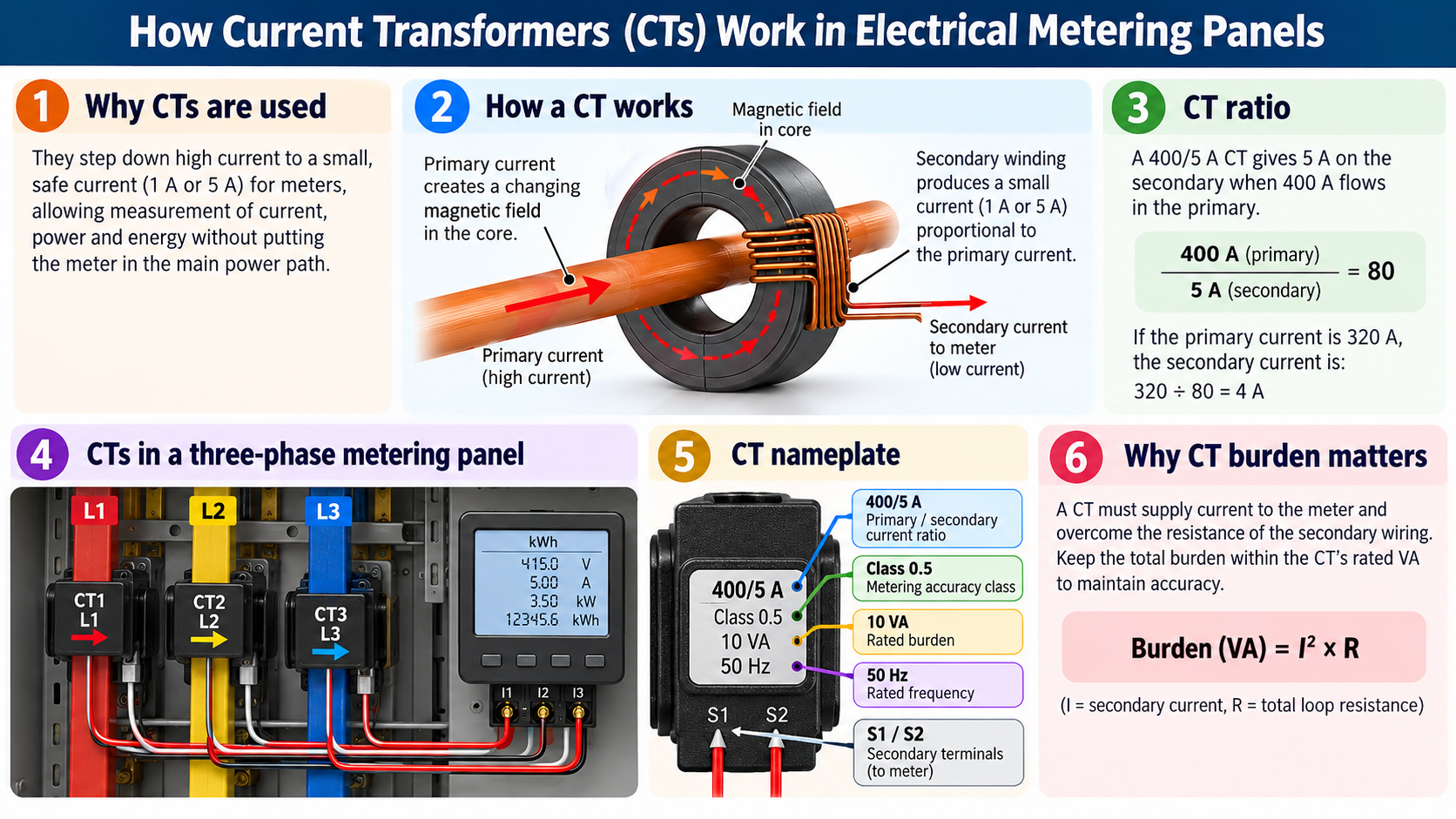
1 Why are CTs used in metering panels?
Electrical distribution panels may carry hundreds or thousands of amperes, but most panel-mounted energy meters and measuring instruments are designed for low-current inputs. A current transformer (CT) provides a scaled current signal that a compatible instrument can use to calculate current, demand, power and energy. By keeping the meter out of the main power path, CT metering also simplifies monitoring of large feeders.
You will typically find CTs inside main distribution boards (MDBs), sub-main distribution boards (SMDBs), generator panels, automatic transfer switch (ATS) panels and industrial power-monitoring panels. In a common three-phase, four-wire arrangement, a dedicated CT is placed around each phase conductor; the meter also needs correctly matched voltage inputs to calculate electrical power and kWh.
2 How does a current transformer work?
A conventional inductive CT works on electromagnetic induction. An AC primary current in a cable or busbar creates a changing magnetic field in the CT core. That changing field induces current in a secondary winding connected to a low-impedance metering circuit. The secondary current is approximately proportional to the primary current within the CT’s specified performance range.
For a ring-type CT, the cable or busbar passing once through the window usually forms one primary turn. The CT secondary has many turns. The turns relationship produces the rated primary-to-secondary current ratio, such as 400/5 A. Standard inductive CTs are for AC measurement; ordinary CTs cannot measure steady DC current. DC applications require other sensing technologies, such as suitable Hall-effect transducers or shunts.
3 Understanding CT ratios: 200/5 A, 400/5 A and more
The CT ratio shows the primary current corresponding to the rated secondary current. A 400/5 A CT produces approximately 5 A secondary current when 400 A flows in the primary conductor under rated conditions. Its nominal ratio multiplier is 400 ÷ 5 = 80. If actual primary current is 320 A, the secondary current is approximately 320 ÷ 80 = 4 A.
4 CT connections in a three-phase energy metering panel
In a typical three-phase, four-wire installation, CT1 surrounds phase L1, CT2 surrounds L2 and CT3 surrounds L3. Each secondary pair (S1 and S2) passes through appropriate CT shorting/test terminals to the matching current input of the meter. Correct phase mapping and polarity are essential because a multifunction meter combines current signals with the corresponding voltage references to calculate active power (kW), reactive power (kVAr), power factor and accumulated energy (kWh).
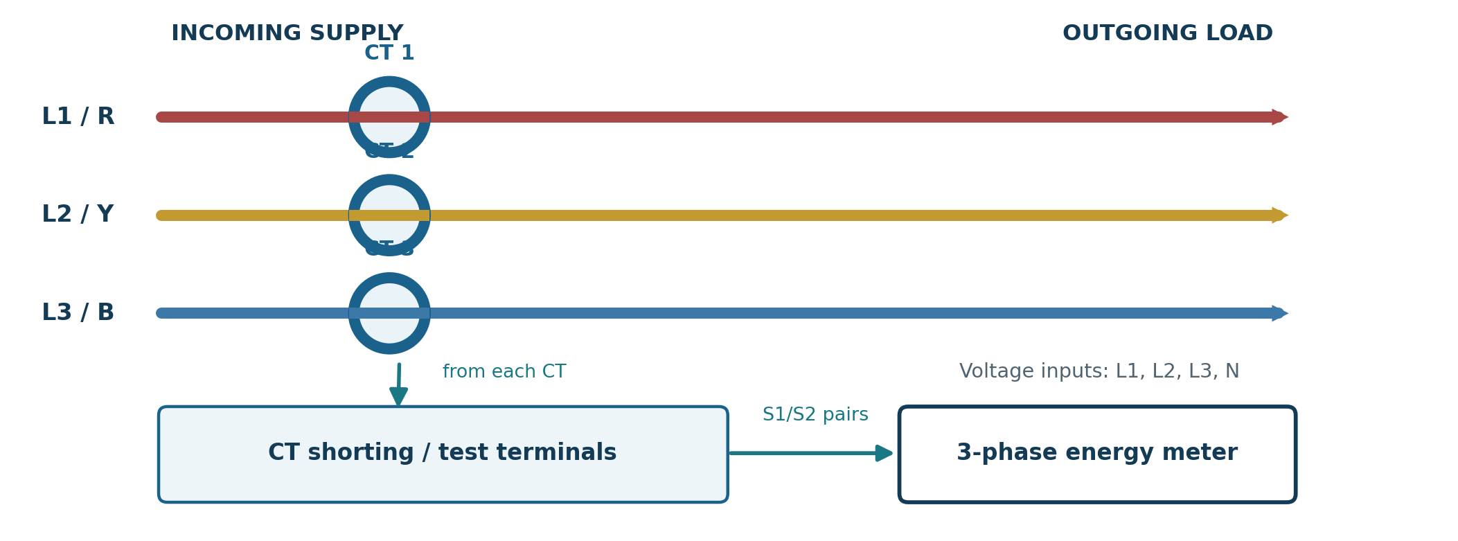
A dedicated CT normally surrounds only the intended phase conductor. Passing all phase conductors together through the same ring produces a different type of measurement and is not the arrangement for individual phase-current metering. Some three-wire systems use different CT configurations; the number and connections must match the selected meter’s approved wiring mode.
5 What do the CT nameplate details mean?
Consider an illustrative CT nameplate reading: “400/5 A • Class 0.5 • 10 VA • 50 Hz”. Every part is relevant to selecting a reliable measurement system.
| Marking | Meaning |
|---|---|
| 400/5 A | 400 A rated primary; 5 A rated secondary current. |
| Class 0.5 | Metering accuracy class; error limits apply under defined conditions - not a blanket guarantee at every load. |
| 10 VA | Rated secondary burden for which accuracy performance is specified. |
| 50 Hz | Rated power frequency; use equipment compatible with the installation. |
| P1 / P2 | Primary polarity/direction marks; normally source/line and load sides respectively. |
| S1 / S2 | Secondary polarity terminals used to preserve correct current and power direction. |
For revenue or billing-related applications, higher precision such as Class 0.2S or 0.5S may be specified. The “S” designation extends defined accuracy performance into lower-current ranges compared with the corresponding ordinary class. Final accuracy requirements should follow the project specification, the utility’s metering requirements, and the applicable standard. Protection-class CTs (for example, 5P or 10P) have different performance objectives and should not be treated as interchangeable with metering-class CTs.
6 Selecting a CT for an LV panel board
Step 1 - Match the meter input technology
Confirm whether the meter requires a conventional 1 A or 5 A current-output CT, a low-voltage output sensor, or a Rogowski coil. These inputs are not automatically interchangeable. Check the meter’s wiring mode, number of measurement elements and CT ratio configuration.
Step 2 - Choose the primary ratio around the real load
Review expected maximum continuous feeder current, normal operating range and future load growth. Select a standard primary rating that can measure the highest intended continuous current without losing useful resolution at ordinary loads. Do not automatically select the CT ratio just because an MCCB has that frame rating. Check the CT manufacturer’s continuous current limits and, separately, its short-time/dynamic withstand ratings.
Step 3 - Choose the accuracy class and burden
For general monitoring, Class 0.5 or Class 1 may be suitable when permitted by the specification. Critical or billing metering may require more stringent classes. The burden meter input plus both secondary leads and connections must be compatible with the CT’s rated VA and its specified accuracy operating range.
Step 4 - Check physical fit and installation conditions
Verify aperture dimensions for the busbar or cable (including insulation), CT mounting clearance, insulation and voltage rating, frequency, environmental conditions, available termination space and the panel’s prospective fault level. Select solid-core, split-core or busbar-mounted formats according to the installation and manufacturer limits.
7 Why CT burden matters: a worked calculation
A CT must supply current to the meter and overcome resistance in the two-wire secondary loop. A simple resistive estimate for wiring burden is VA = I² × R, where I is rated secondary current and R is total loop resistance. Add the meter input burden and any other approved series-device burden. Obtain actual conductor resistance, wiring temperature, and meter input VA from their datasheets.
| Example assumptions | Worked result |
|---|---|
| CT secondary | 5 A |
| Copper leads | 2.5 mm²; 15 m one way = 30 m loop |
| Illustrative resistance at 20°C | ≈ 7.4 Ω/km × 0.030 km = 0.222 Ω |
| Secondary lead burden | 5² × 0.222 ≈ 5.55 VA |
| Illustrative meter burden | 0.50 VA (verify actual datasheet) |
| Total estimated burden | ≈ 6.05 VA, before margin / hot-wire effects |
A CT with a suitable 10 VA output may be worth evaluating for this example, provided its full accuracy, range and manufacturer requirements are met. This is not a final design approval. At the same loop resistance, a 1 A secondary generates only 0.222 VA of wiring loss-25 times less than a 5 A secondary at rated current. That is why 1 A systems are often helpful for longer meter cable runs.
Conclusion
Current transformers are small components with a major role in reliable electrical metering. The most important design decisions are the CT ratio, the compatible meter input, metering accuracy class, burden, physical arrangement and safe secondary wiring. When these are correctly coordinated and installation polarity and meter configuration are checked, a CT-based system can provide accurate, useful data for managing an LV distribution network.