
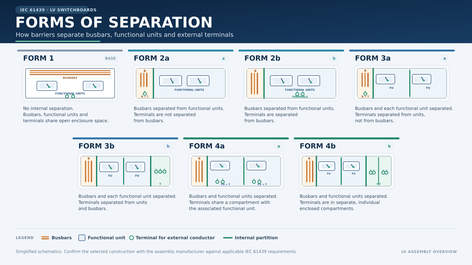
Form of separation refers to the internal segregation within a low-voltage (LV) switchboard, ensuring that various elements, such as busbars, functional units, and terminals, are properly partitioned to ensure safety and reliability. According to IEC 61439-1, the separation of these elements can be claimed if one or more of the following criteria are met:
Form 1: In most installations, no specific partitioning is required, and electrical switchboards of the Form 1 type are acceptable. However, to comply with safety standards, the switchboard must have a front plate or other equivalent means to ensure users cannot access live parts.
Form 2: Introduces partitioning between busbars to provide segregation within the switchboard.
Form 3a and 3b: Provides separation for functional units from each other and from the busbars. Additionally, connecting terminals are separated from the busbars for added safety.
Form 4a and 4b: Provides the highest level of separation, where functional units are separated from each other and from the busbars, while connecting terminals are separated both from each other and from the busbars.
These forms of separation are critical for the safety of maintenance personnel, ensuring that:
- Parts not under maintenance do not create hazardous situations in parts that are being maintained.
- Maintenance in one section should not create dangers in another (e.g., a screw or tool falling into another part).
- A fault, such as an arc, in one section should not impact or spread to other sections.
This internal partitioning enhances operational safety by minimizing the risk of electrical hazards during both normal operation and maintenance activities.
| Form | Diagram | Main Criteria | Sub-Criteria |
|---|---|---|---|
| Form 1 | 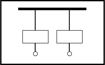 | No Separation | - |
| Form 2a | 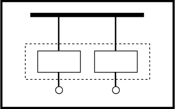 | Separation of busbars from the functional units | Terminals for external conductors not separated from busbar |
| Form 2b | 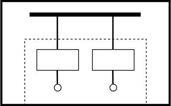 | Separation for busbars from the functional units | Terminals for external conductors separated from busbar |
| Form 3a |  | Separation of busbars from the functional units and separation of all functional units from one another. Separation of the terminals for external conductors from the functional units, but not from each other. | Terminals for external conductors not separated from busbar |
| Form 3b | 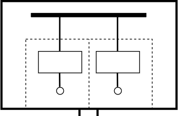 | Separation of busbars from the functional units and separation of all functional units from one another. Separation of the terminals for external conductors from the functional units, but not from each other. | Terminals for external conductors separated from busbar |
| Form 4a | 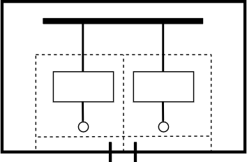 | Separation of busbars from the functional units and separation of all functional units from one another, including the terminals for external conductors which are an integral part of the functional unit. | Terminals for external conductors in same compartment as the associated functional unit. |
| Form 4b | 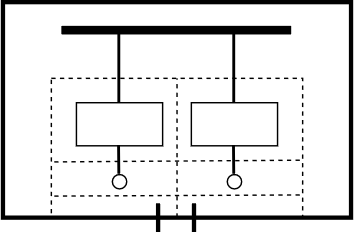 | Separation of busbars from the functional units and separation of all functional units from one another, including the terminals for external conductors which are an integral part of the functional unit. | Terminals for external conductors are not in same compartment as the associated functional units, but in individual, separate, enclosed protected spaces or compartments. |
Symbol Keys
 Internal Separation
 Enclosure
 Cable Glands
 Busbar
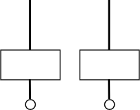 Functional units including terminals for external conductors
Our Free-Standing Panels are intelligently designed to provide a versatile and secure solution for housing electrical and control systems. Whether for industrial applications, data centers, or commercial settings, our panels are crafted with a focus on functionality and adaptability.